





Topcon CR-P1 for MEP and Building Services Coordination Malaysia - 3D Laser Scanning Applications

Topcon CR-P1 for MEP and Building Services Coordination Malaysia - 3D Laser Scanning Applications
Introduction
Mechanical, Electrical and Plumbing (MEP) coordination is an important part of construction, renovation and industrial facility projects in Malaysia.
Engineers and contractors often need to install air-conditioning ductwork, water pipes, cable trays, electrical equipment and other building services within limited available space.
Existing buildings can present additional challenges because original drawings may be incomplete or no longer reflect the actual site conditions.
3D laser scanning can support MEP coordination by capturing extensive spatial measurements of accessible and visible building geometry.
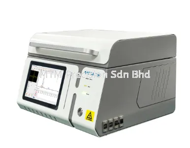
The Topcon CR-P1 3D Laser Scanner may be considered for reality capture applications involving building services documentation, renovation planning and engineering coordination, subject to verified manufacturer capabilities and project requirements.
This guide explains how point cloud surveys can support MEP projects, how scanning data is used during coordination and what limitations engineers should understand.
It describes general 3D laser scanning workflows and does not claim unverified Topcon CR-P1 technical specifications, software functions or certifications.
What Is MEP Coordination?
MEP coordination is the process of arranging mechanical, electrical and plumbing systems so that they can be installed, operated and maintained within the available building space.
Typical systems include:
Air-conditioning ducts.
Ventilation equipment.
Water supply pipes.
Drainage pipes.
Electrical cable trays.
Conduits.
Fire protection pipework.
Pumps and mechanical equipment.
Plant room installations.
Other building services.
Coordination may involve architects, structural engineers, MEP consultants, BIM teams and installation contractors.
A coordinated design must consider physical space, equipment access, maintenance requirements and applicable engineering standards.
Why Accurate Existing Building Geometry Matters
MEP drawings may not always reflect the actual geometry of an existing building.
During renovation or retrofit work, contractors may discover that beams, columns, existing services or ceiling spaces differ from the available drawings.
These differences can create installation conflicts.
For example, a proposed ventilation duct may intersect an existing beam or occupy the same space as a cable tray.
A suitable existing condition survey can provide more reliable geometric information before installation planning begins.
3D laser scanning may support this process by recording visible site geometry for later review.
However, the survey must be appropriately registered, verified and processed.
How 3D Laser Scanning Supports MEP Coordination
A 3D laser scanner captures spatial measurements from visible surfaces within its measurement path.
These measurements can be processed into a point cloud representing the surveyed environment.
For MEP applications, a point cloud may provide references for:
Existing ductwork locations.
Visible piping arrangements.
Cable tray positions.
Structural columns and beams.
Plant room geometry.
Equipment clearances.
Ceiling spaces.
Accessible service corridors.
Engineers can use suitably processed point clouds to help evaluate the available space for proposed installations.
The scanner does not automatically identify pipe contents, electrical circuits, concealed services or compliance with engineering requirements.
Topcon CR-P1 for HVAC Ductwork Coordination
Heating, Ventilation and Air Conditioning (HVAC) installations may require careful coordination with structural and architectural features.
Large ventilation ducts can compete for space with beams, ceilings, cable trays and other building services.
A 3D survey may help document:
Existing visible duct routes.
Accessible ceiling geometry.
Equipment locations.
Structural obstructions.
Plant room layouts.
Potential installation corridors.
The resulting point cloud can support design review and geometric coordination.
However, a point cloud does not automatically determine airflow performance, duct sizing or HVAC system suitability.
Those decisions require appropriate engineering calculations and design procedures.
Topcon CR-P1 for Plumbing and Pipework Documentation
Plumbing and mechanical piping projects may involve complex existing installations.
For example, a building refurbishment may require new water pipes or drainage routes through an occupied service area.
Laser scanning can help document visible pipe geometry and surrounding structures.
Potential applications include:
Plant room surveys.
Exposed water pipe documentation.
Accessible drainage pipe layouts.
Pump installation planning.
Pipe support coordination.
Equipment replacement projects.
The point cloud represents measured visible geometry.
It cannot directly determine pipe wall thickness, internal condition, fluid contents or concealed routing.
Additional inspections or appropriate testing methods may be necessary.
Topcon CR-P1 for Electrical Cable Tray Coordination
Electrical installations may require cable trays, conduits, distribution equipment and other components to fit within existing spaces.
A 3D laser scanning survey may help record:
Visible cable tray routes.
Accessible equipment locations.
Structural obstructions.
Ceiling service zones.
Electrical room geometry.
Available installation clearances.
The data may support spatial planning and coordination between electrical and mechanical contractors.
However, scanning does not establish electrical safety, circuit identification, cable loading or regulatory compliance.
These matters require qualified electrical engineering assessment.
Topcon CR-P1 for Fire Protection Services
Fire protection systems may include exposed sprinkler pipes, valves, pumps and related building services.
A point cloud may support geometric documentation of visible installations.
For example, an engineering team may use a registered point cloud to review existing pipe positions before planning modifications.
However, laser scanning does not verify system pressure, hydraulic performance, fire protection coverage or compliance with applicable codes.
The required design and inspection work must be performed separately.
Topcon CR-P1 for Plant Rooms and Mechanical Equipment
Mechanical plant rooms often contain closely arranged equipment and services.
A survey may need to document:
Pumps.
Chillers.
Air handling equipment.
Visible piping.
Ductwork.
Structural features.
Equipment foundations.
Accessible maintenance spaces.
A point cloud can provide a geometric reference for equipment replacement or layout planning.
Engineers must still verify equipment dimensions, installation requirements and maintenance clearances.
Do not assume that every critical surface can be measured when equipment or structures obstruct the scanner's line of sight.
Topcon CR-P1 for Data Centre Building Services
Data centres can contain dense arrangements of mechanical, electrical and cooling infrastructure.
Potential survey requirements may include documentation of accessible:
Equipment room geometry.
Cooling system installations.
Cable trays.
Overhead service routes.
Structural features.
Equipment access corridors.
Mechanical plant areas.
3D laser scanning may support geometric coordination during renovation or infrastructure upgrades.
However, access restrictions, operational continuity and information security are particularly important.
Scanning equipment and workflows should be approved by the facility operator.
A point cloud does not establish electrical capacity, cooling performance, network connectivity or system redundancy.
Topcon CR-P1 for Factory MEP Retrofit Projects
Factories may require changes to ventilation, piping, electrical distribution or equipment layouts.
Existing facilities can be difficult to document because of complex machinery and limited access.
A 3D laser scanning survey may provide geometric references for:
Visible pipe routes.
Overhead ductwork.
Cable tray arrangements.
Machinery surroundings.
Equipment installation areas.
Structural clearances.
Factory building geometry.
The survey team should coordinate with plant management and follow site safety procedures.
The Topcon CR-P1 must not be assumed suitable for hazardous or explosive atmospheres without verified manufacturer approval and applicable certification.
Step 1 - Define the MEP Survey Scope
Before scanning, identify which systems and areas require documentation.
Important questions include:
Which building services are relevant?
Is the project a new installation or retrofit?
Which floors or rooms are included?
Are overhead services important?
What accuracy is required?
Are existing drawings available?
Will the data be used for BIM coordination?
What deliverables are expected?
The scope should identify any inaccessible or excluded areas.
Step 2 - Review Existing MEP Drawings
Existing architectural and MEP drawings may help identify survey requirements.
However, drawings should not automatically be treated as accurate representations of current site conditions.
Renovation work and undocumented modifications may have changed the installation layout.
The project team should compare available drawings with accessible site information and identify areas requiring verification.
Step 3 - Plan Site Access and Safety
MEP surveys may take place in ceiling spaces, plant rooms, industrial facilities and occupied buildings.
Surveyors should review:
Site access permissions.
Working areas.
Equipment hazards.
Moving machinery.
Electrical safety restrictions.
Confined or restricted spaces.
Operational schedules.
Data confidentiality requirements.
Scanning must not interfere with live equipment or compromise site safety.
Step 4 - Plan Scanning Positions
Scanner positions should provide suitable coverage of the required visible geometry.
Complex service areas may require multiple scanning viewpoints because pipes, ducts and equipment can obstruct one another.
The survey team should consider:
Visibility of critical services.
Overlap between scanning positions.
Access around equipment.
Overhead geometry.
Restricted areas.
Survey control requirements.
The number of scans depends on site complexity and the verified capabilities of the selected instrument.
Step 5 - Establish Survey Control When Required
Some MEP coordination projects require point cloud data to align with established building or construction coordinates.
Survey control may be necessary when the project involves:
Large facilities.
Multiple floors.
Building extensions.
Coordination with structural surveys.
Repeated surveys.
Precise equipment installation references.
A total station may be used for conventional control measurements when appropriate.
For example, Topcon GM Series total stations can support selected surveying tasks, subject to model specifications and project requirements.
The scanning dataset must still be independently verified against the agreed tolerances.
Step 6 - Capture Visible MEP Geometry
The scanning team can collect spatial measurements using the manufacturer's approved operating procedures.
Potential survey targets include:
Exposed pipes.
Ventilation ducts.
Cable trays.
Equipment surfaces.
Structural columns.
Ceiling geometry.
Service corridors.
Plant room layouts.
The Topcon CR-P1 scanning procedure and supported operating settings must be confirmed using official manufacturer documentation.
Do not assume that the scanner can measure through walls, insulation or other opaque barriers.
Step 7 - Register and Process the Point Cloud
Individual scans may require registration into a common spatial reference.
Registration can use suitable overlapping geometry, supported reference targets, survey control or other validated methods.
The processed point cloud should be checked for:
Registration consistency.
Correct coordinates.
Missing geometry.
Unwanted measurements.
Adequate service coverage.
Project accuracy requirements.
Specific Topcon CR-P1 registration software and supported export formats must be verified.
Step 8 - Prepare MEP Coordination Deliverables
The required deliverables should be agreed before the survey begins.
Possible outputs include:
Registered point cloud datasets.
Existing service layout drawings.
Plant room as-built documentation.
Sections through service zones.
CAD references.
BIM coordination models.
Geometric installation planning references.
Creating a BIM model from point cloud data requires additional interpretation and modelling work.
A scanner does not automatically produce a complete MEP BIM model.
Step 9 - Review Potential Geometric Clashes
A processed point cloud may be compared with proposed installation geometry using suitable software.
This can help identify potential spatial conflicts involving:
Ductwork and beams.
Pipework and columns.
Cable trays and ventilation ducts.
Equipment and access spaces.
New services and existing installations.
However, geometric clash identification is not the same as a complete engineering design review.
Clearances, access, regulations and system performance must be evaluated separately.
Step 10 - Verify Critical Dimensions Before Installation
Before installing equipment or modifying building services, critical dimensions should be checked using an appropriate measurement method.
Examples include:
Equipment installation clearances.
Pipe connection locations.
Structural opening dimensions.
Available ceiling space.
Support locations.
Maintenance access requirements.
The required verification method depends on the project tolerances and engineering responsibilities.
Point cloud density alone does not guarantee accuracy.
3D Laser Scanning vs Traditional MEP Site Measurement
Traditional MEP site measurement may use laser distance meters, tape measures, levels and total stations.
These methods remain appropriate for many projects.
Traditional measurement may be sufficient when only a few dimensions or connection points are required.
3D laser scanning may be considered when the site contains extensive visible services, complex geometry or multiple installation constraints.
A combined approach can also be effective.
For example, a point cloud may provide overall spatial documentation while independent measurements verify critical connection points.
The best approach depends on project requirements, equipment suitability and available resources.
How Point Clouds Support Scan-to-BIM for MEP
Scan-to-BIM involves using surveyed spatial information as a reference for creating or updating building information models.
For MEP applications, modelling teams may interpret visible pipes, ducts, cable trays and equipment from a point cloud.
The process may involve:
Point cloud registration.
Coordinate verification.
Identification of visible components.
Creation of suitable model geometry.
Review of geometric accuracy.
Coordination with proposed systems.
Not every visible object can be automatically identified or modelled.
The level of detail and modelling responsibilities must be agreed with the client.
Common MEP Laser Scanning Problems
Problem 1 - Services Are Hidden Above Ceilings
Suspended ceilings may obstruct the scanner's view.
Solution: Arrange authorized access and document inaccessible areas.
Problem 2 - Pipes and Ducts Block One Another
Complex installations can create missing geometry.
Solution: Plan additional scanning positions where safe and practical.
Problem 3 - Reflective Metal Surfaces
Some metal surfaces may affect optical measurement quality.
Solution: Review manufacturer guidance and independently verify critical dimensions.
Problem 4 - Incorrect Scan Registration
Misaligned scans can affect service locations.
Solution: Review registration quality and independent reference measurements.
Problem 5 - Outdated MEP Drawings
Existing drawings may not reflect previous modifications.
Solution: Verify the current visible geometry through a suitable survey.
Problem 6 - Unclear BIM Requirements
The client may expect a complete model when only a point cloud was included.
Solution: Define deliverables and modelling responsibilities before work begins.
Problem 7 - Incomplete Installation Clearances
Visible geometry alone may not establish all required maintenance and operational clearances.
Solution: Verify clearances against equipment documentation and engineering requirements.
Problem 8 - Unsafe Scanning Locations
Live electrical equipment, moving machinery and restricted areas may create hazards.
Solution: Follow site procedures and use only approved equipment and access methods.
Can 3D Laser Scanning Reduce MEP Installation Clashes?
A properly planned scanning workflow can provide useful geometric references that help project teams identify potential spatial conflicts before installation.
However, scanning does not eliminate all installation clashes.
Results depend on:
Survey coverage.
Measurement accuracy.
Registration quality.
Correct coordinate references.
Appropriate modelling.
Current design information.
Engineering review.
Verification of critical dimensions.
A point cloud should support professional coordination rather than replace engineering judgment.
Who Should Consider 3D Laser Scanning for MEP Projects?
Potential users include:
MEP consultants.
Mechanical contractors.
Electrical contractors.
Plumbing contractors.
HVAC installation companies.
BIM coordination teams.
Construction contractors.
Factory engineering departments.
Data centre facility teams.
Building renovation companies.
The decision to purchase scanning equipment should consider project demand, technical capability, processing requirements and long-term ownership costs.
For occasional projects, specialist scanning services may be a practical alternative.
What to Check Before Buying the Topcon CR-P1 for MEP Work
Before selecting the Topcon CR-P1, buyers should verify:
Official measurement accuracy specifications.
Suitable working distances.
Coverage requirements.
Software compatibility.
Point cloud export formats.
Registration workflow.
CAD and BIM integration requirements.
Computer processing resources.
Operator training.
Warranty and technical support.
Applicable service arrangements.
Current product availability.
All model-specific capabilities should be confirmed using official Topcon documentation.
Topcon CR-P1 Malaysia - Product Enquiries
MTM Precision Sdn Bhd supplies surveying instruments and provides surveying instrument service and calibration support in Malaysia.
MEP contractors, HVAC engineers, electrical contractors, BIM consultants, construction companies and industrial facility teams interested in the Topcon CR-P1 3D Laser Scanner may contact MTM Precision to discuss their intended applications.
Enquiries may include MEP coordination, existing building surveys, factory retrofits, plant room documentation, point cloud workflows and reality capture equipment selection.
Product availability, quotation arrangements, software compatibility, supply conditions and applicable technical support are subject to confirmation.
The Topcon CR-P1 is not represented as a ready-stock product at MTM Precision.
Frequently Asked Questions
Q1. What is MEP coordination in construction?
MEP coordination is the process of arranging mechanical, electrical and plumbing systems so that they fit within the building and meet relevant engineering requirements.
Q2. How does 3D laser scanning help MEP coordination?
It can capture visible building and service geometry for use as a reference during installation planning, as-built documentation and geometric coordination.
Q3. Can the Topcon CR-P1 be used for MEP surveys?
The Topcon CR-P1 may be considered for reality capture applications, subject to verified manufacturer capabilities and project requirements.
Q4. Can laser scanning detect pipes hidden inside walls?
No. Conventional optical laser scanning records visible surfaces and cannot directly detect concealed pipes or cables.
Q5. Can a point cloud help identify ductwork clashes?
A suitably processed point cloud can provide geometric references for identifying potential conflicts when compared with proposed installation geometry using appropriate software.
Q6. Does a 3D scanner automatically create an MEP BIM model?
No. BIM modelling requires additional software, interpretation and verification.
Q7. Can 3D laser scanning be used in mechanical plant rooms?
It may support documentation of accessible plant room geometry, subject to instrument suitability, site access and safety requirements.
Q8. Is laser scanning suitable for data centre upgrades?
It may support geometric documentation and coordination, subject to facility approval, security requirements and verified equipment capabilities.
Q9. Can a laser scanner measure through ceiling panels?
No. Opaque ceiling panels obstruct direct optical measurement of concealed services.
Q10. How accurate must an MEP point cloud be?
Required accuracy depends on the project, installation tolerances and intended deliverables. The measurement method should be verified against agreed requirements.
Q11. Can a total station be used together with a 3D laser scanner?
Yes. A total station may support survey control and selected coordinate measurements while a scanner captures extensive visible geometry.
Q12. Does MTM Precision provide Topcon CR-P1 calibration?
MTM Precision provides surveying instrument service and calibration support. Specific CR-P1 calibration capability has not been confirmed and must be checked before arranging service.
Q13. Is the Topcon CR-P1 available from ready stock at MTM Precision?
No ready-stock claim is made. Customers should contact MTM Precision to confirm availability and supply arrangements.
Q14. Where can I enquire about the Topcon CR-P1 in Malaysia?
Contact MTM Precision Sdn Bhd in Puchong, Selangor, to discuss application requirements and request product information or quotation arrangements.
Contact MTM Precision
MTM Precision Sdn. Bhd.
Showroom & Service Centre
No. 29-1 & 29-2, Jalan Bandar 18,
Pusat Bandar Puchong,
47160 Puchong, Selangor, Malaysia.
Website: www.mtmpre.com.my
Email: mtmpre@yahoo.com
WhatsApp: +6016-660 7346
MTM Precision welcomes surveying instrument enquiries from Kuala Lumpur, Selangor, Johor, Penang, Perak, Negeri Sembilan, Melaka, Pahang, Terengganu, Kelantan, Kedah, Perlis, Sabah and Sarawak.
SEO Meta Description
Topcon CR-P1 MEP coordination guide Malaysia. Explore 3D laser scanning for HVAC, piping, cable trays, plant rooms and building services surveys.
Internal Linking Suggestions
1. Topcon CR-P1 3D Laser Scanner Malaysia - Features, Applications and Buying Guide
2. Topcon CR-P1 3D Laser Scanner for Building Survey and As-Built Documentation Malaysia
3. Topcon CR-P1 for BIM and Scan-to-BIM Projects Malaysia
4. Topcon CR-P1 for Construction Site Survey and Progress Documentation Malaysia
5. Topcon CR-P1 for Industrial Plant and Factory 3D Scanning Malaysia
6. Topcon CR-P1 vs Total Station Malaysia - Which Surveying Instrument Should You Choose?
7. How to Choose a 3D Laser Scanner for Surveying and Construction Malaysia - Topcon CR-P1 Buying Guide
8. How to Use a 3D Laser Scanner for Building and Construction Surveys Malaysia - Topcon CR-P1 Workflow Guide
9. Topcon CR-P1 Point Cloud Registration and Data Processing Malaysia - Common Problems and Solutions
10. Topcon CR-P1 3D Laser Scanning Accuracy Malaysia - Common Measurement Errors and Quality Control
11. Topcon CR-P1 for Renovation and Existing Building Measurement Malaysia - 3D As-Built Survey Guide
12. Topcon GM-55 vs GM-65 Total Station Malaysia
13. Topcon GM-55, GM-62 and GM-65 Ready Stock Malaysia
14. Total Station Calibration Malaysia
15. Total Station Repair and Service Malaysia
16. 3D Laser Scanner Malaysia - Complete Buying Guide
27 Oct 2026


