





Complete Guide to Fiber Optic Testing Equipment Malaysia - NOYAFA NF-8607

Complete Guide to Fiber Optic Testing Equipment Malaysia - NOYAFA NF-8607
Introduction
Reliable fiber optic communication is essential for telecommunications, data centres, commercial buildings, industrial facilities and modern network infrastructure.
When fiber optic links experience signal loss, unstable communication or unexpected interruptions, technicians need suitable instruments to investigate possible causes.
However, different optical testing instruments provide different types of diagnostic information.
An Optical Time Domain Reflectometer (OTDR) can analyse certain optical events along a fiber link, while an optical power meter measures optical power at a measurement point.
A visual fault locator may help identify certain accessible fiber faults, but it cannot replace comprehensive optical measurements.
Choosing the right Fiber Optic Testing Equipment Malaysia therefore requires an understanding of testing methods, instrument limitations and actual project requirements.
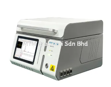
The NOYAFA NF-8607 Multifunction Fiber Optic Tester is one model that buyers may consider when evaluating optical fiber testing equipment.
Its exact specifications, supported functions and compatibility must be confirmed using current manufacturer documentation.
This complete guide explains the major categories of fiber optic testing equipment, common applications, important technical specifications, troubleshooting considerations and purchasing decisions.
It is designed for fiber optic contractors, telecommunications technicians, data centre maintenance teams and industrial network professionals in Malaysia.
1. What Is Fiber Optic Testing?
Fiber Optic Testing involves evaluating selected characteristics of an optical fiber connection or network.
The testing objective depends on the installation and maintenance requirements.
Common objectives include:
Investigating optical signal levels.
Evaluating fiber attenuation.
Identifying certain optical events.
Investigating possible cable damage.
Assessing optical connection conditions.
Supporting installation acceptance.
Maintaining fiber optic infrastructure.
Documenting selected optical measurements.
Different objectives may require different instruments.
A single measurement cannot automatically confirm every aspect of fiber link performance.
2. Why Fiber Optic Testing Is Important in Malaysia
Fiber Optic Testing Malaysia is relevant to several infrastructure sectors.
Telecommunications Networks
Fiber optic connections are used in access networks, distribution infrastructure and backbone communication systems.
Data Centres
Fiber connections support communication between compatible network and computing equipment.
Commercial Buildings
Fiber optic links may connect network equipment rooms and building distribution systems.
Industrial Facilities
Optical fiber may be used in selected industrial communication networks.
CCTV Infrastructure
Fiber connections may support communication between suitable network equipment used in surveillance installations.
Utility Infrastructure
Optical fiber may be used in selected utility communication applications.
Reliable testing helps technicians investigate problems and assess whether the available measurement information meets project requirements.
3. Main Types of Fiber Optic Testing Equipment
The main categories of Fiber Optic Test Equipment include:
EquipmentMain PurposeImportant LimitationOTDRAnalyse optical events along a fiber linkCannot identify every fault or its exact physical causeOptical Power MeterMeasure optical power at a pointDoes not directly locate a fiber faultOptical Light SourceProvide a suitable optical signal for testingRequires an appropriate measurement methodVisual Fault LocatorHelp identify certain accessible fiber faults or pathsCannot detect every fault or quantify insertion lossFiber Connector Inspection EquipmentExamine connector end-face conditionsDoes not measure complete link performance
The correct equipment depends on the diagnostic objective.
Some projects may require multiple instruments and measurement methods.
4. What Is an OTDR Fiber Optic Tester?
An OTDR (Optical Time Domain Reflectometer) is an optical instrument used to analyse events along a fiber link.
An OTDR introduces optical pulses into a fiber and examines returned optical signals associated with backscattering and reflections.
Under suitable conditions, an OTDR may provide information about:
Fiber attenuation.
Connector-related events.
Splice-related events.
Reflective events.
Possible fiber breaks.
Approximate distances to identifiable events.
The information is commonly presented as an OTDR trace.
What an OTDR Cannot Automatically Do
An OTDR cannot guarantee identification of every optical fault.
It also cannot automatically determine the exact physical cause of an abnormal event.
Measurement performance depends on the instrument, fiber characteristics and testing conditions.
5. How to Choose an OTDR Fiber Optic Tester
When selecting an OTDR Fiber Optic Tester Malaysia, buyers should evaluate the intended optical link.
Important considerations include:
Supported Fiber Types
Confirm whether the instrument is compatible with the intended single-mode or multimode fiber.
Testing Wavelengths
Verify the supported wavelengths and their relevance to the application.
Dynamic Range
Consider the attenuation characteristics of the fiber route.
Event Dead Zone
Evaluate the ability to distinguish certain closely spaced reflective events.
Attenuation Dead Zone
Consider limitations affecting loss measurements near optical events.
Distance Measurement Characteristics
Review the manufacturer's definitions and measurement conditions.
Optical Interfaces
Confirm connector compatibility and required accessories.
Documentation Requirements
Determine whether the instrument provides the measurement information required by the project.
A long advertised testing distance does not automatically mean that an OTDR is suitable for every installation.
6. NOYAFA NF-8607 vs NF-981 vs NF-983 - What Should Buyers Compare?
Customers researching NOYAFA fiber optic testing equipment may compare the NOYAFA NF-8607, NOYAFA NF-981 and NOYAFA NF-983.
However, a model name or general product description does not establish the technical differences between instruments.
Buyers should compare verified manufacturer documentation for the exact supplied versions.
Comparison FactorWhat to VerifyOptical Testing FunctionsWhich functions are actually includedSupported Fiber TypesSingle-mode, multimode or other specified compatibilityTesting WavelengthsManufacturer-confirmed wavelengthsDynamic RangeVerified values and measurement conditionsEvent Dead ZoneManufacturer-confirmed performanceAttenuation Dead ZoneManufacturer-confirmed performanceOptical InterfacesCompatible connectors and accessoriesAdditional Network FunctionsActual supported capabilitiesMeasurement DocumentationAvailable records and reportingWarrantyApplicable supplier and manufacturer terms
The best choice depends on the required measurements rather than the model name alone.
MTM Precision can assist customers with product enquiries and comparison of available manufacturer information.
7. Fiber Optic Cable Fault Detection
Fiber Optic Cable Fault Detection Malaysia involves investigating abnormalities that may affect optical communication.
Possible causes of communication problems include:
Fiber cable damage.
Connector contamination.
Poor optical connections.
Excessive bending.
Splice-related losses.
Optical transceiver problems.
Network equipment faults.
An OTDR may help identify certain optical events.
However, not every network interruption is caused by a fiber cable fault.
Additional inspection or diagnostic methods may be required.
8. Understanding OTDR Trace Interpretation
An OTDR Trace represents returned optical signal information along the tested fiber.
The trace may contain changes associated with attenuation, reflection or other optical events.
Reflective Events
Reflective events may be associated with certain optical interfaces or discontinuities.
A reflection does not automatically indicate a defective connector.
Non-Reflective Events
Some changes in optical attenuation may appear without a strong reflection.
Their interpretation depends on the measurement conditions and fiber characteristics.
End-of-Fiber Events
An OTDR may identify an event associated with the end of a fiber under suitable conditions.
However, event interpretation can be affected by instrument limitations.
Important Limitation
An OTDR trace provides diagnostic information, not guaranteed identification of every physical defect.
9. 1310nm vs 1550nm OTDR Testing
1310nm vs 1550nm OTDR Testing is a common topic in conventional single-mode fiber applications.
Both wavelengths are widely associated with optical fiber testing.
In many conventional single-mode fibers, attenuation is generally lower at 1550nm than at 1310nm.
The 1550nm wavelength may also be more sensitive to certain bending-related losses.
Comparison Factor1310nm1550nmCommon ApplicationConventional single-mode fiber testingConventional single-mode fiber testingFiber AttenuationGenerally higher than at 1550nm in many conventional single-mode fibersGenerally lower in many conventional single-mode fibersBend SensitivityOften less sensitive to certain bending lossesOften more sensitive to certain bending lossesMeasurement InterpretationDepends on the fiber and instrumentDepends on the fiber and instrument
Differences between wavelength measurements do not automatically prove that a particular fault exists.
The supported wavelengths and instrument performance must be verified.
10. Optical Power Meter vs OTDR
An Optical Power Meter (OPM) and an OTDR provide different measurement information.
Optical Power Meter
An OPM measures optical power at a measurement point.
It may support optical signal level investigation and appropriate insertion-loss testing.
OTDR
An OTDR analyses optical events along a fiber link.
It may provide distance-related information about certain identifiable events.
Which Instrument Should You Choose?
Choose according to the required measurement.
For example, investigating received optical power is different from analysing the location of optical events.
Some applications require both types of information.
An OTDR trace is not automatically a substitute for reference-based insertion-loss testing.
11. Understanding Fiber Optic Insertion Loss
Fiber Optic Insertion Loss describes the reduction in optical power associated with a component or optical path under defined measurement conditions.
Relevant contributors may include:
Fiber attenuation.
Connector losses.
Splice losses.
Passive optical components.
Other link-related conditions.
Suitable insertion-loss testing commonly uses an optical light source, optical power meter and an appropriate reference method.
Important Limitation
A single optical power reading does not automatically establish the insertion loss of an installed fiber link.
Project acceptance requirements may specify particular measurement methods.
12. Visual Fault Locator for Fiber Troubleshooting
A Visual Fault Locator (VFL) introduces visible light into a compatible optical fiber.
Under suitable conditions, it may help identify certain accessible faults or fiber paths.
Potential applications include:
Patch cord identification.
Selected fiber path verification.
Investigation of certain accessible cable defects.
Short fiber maintenance support.
VFL Limitations
A VFL cannot reliably detect every optical fault.
Some cable jackets prevent visible light from being observed.
Ambient lighting may also affect visibility.
A VFL does not quantify insertion loss or provide OTDR event analysis.
The availability of a VFL function in any particular multifunction tester must be verified.
13. Fiber Optic Testing for Data Centres
Data Centre Fiber Optic Testing Malaysia may involve short links, patch panels and closely spaced optical interfaces.
Important considerations include:
Fiber type compatibility.
Connector conditions.
Optical power measurement.
Short-link testing requirements.
Event dead-zone performance.
Attenuation dead-zone performance.
Active network safety.
Maintenance documentation.
An OTDR intended for longer fiber routes may not necessarily provide the event separation needed for certain short connections.
Data centre technicians should select equipment according to the actual link architecture.
14. Fiber Optic Testing for Telecom Contractors
Fiber Optic Testing for Telecom Contractors Malaysia may involve access networks, distribution systems and longer fiber routes.
Typical applications include:
FTTH infrastructure.
Telecommunications backbone links.
Underground fiber routes.
Aerial fiber infrastructure.
Optical distribution networks.
Fiber maintenance and fault investigation.
Important equipment considerations include:
Fiber route length.
Optical attenuation.
Dynamic range.
Testing wavelengths.
Dead-zone performance.
Optical splitter conditions.
Network operating status.
Required documentation.
Some Passive Optical Network (PON) applications may require specialized instruments or approved testing methods.
A general-purpose OTDR should not automatically be assumed suitable for every active PON network.
15. Understanding OTDR Dead Zone
OTDR Dead Zone describes a limitation affecting the ability to distinguish or measure certain optical events located close together.
Two important parameters are:
Event Dead Zone
This relates to the ability to distinguish closely spaced reflective events.
Attenuation Dead Zone
This relates to the ability to measure loss near an optical event.
These parameters describe different limitations.
Why Dead Zone Matters
Dead-zone performance is particularly relevant to:
Data centre patch panels.
Short fiber links.
Equipment room connections.
Closely spaced optical interfaces.
Buyers should verify both specifications when evaluating an OTDR.
16. Understanding OTDR Dynamic Range
OTDR Dynamic Range is related to the instrument's ability to analyse returned optical signals over a range of signal levels.
As optical signals travel through a fiber, attenuation reduces the strength of returned signals.
Dynamic range influences how much attenuation can be examined before the returned signal becomes difficult to distinguish from noise.
Why Dynamic Range Matters
Dynamic range is relevant to:
Longer fiber routes.
Higher-loss optical links.
Telecommunications backbone testing.
Networks containing passive optical components.
However, higher dynamic range does not automatically guarantee better performance for every application.
Dead-zone performance and other instrument characteristics also matter.
17. OTDR Maximum Range vs Actual Testing Capability
An advertised OTDR Maximum Testing Range should not be interpreted as a guarantee that every optical event can be identified throughout that distance.
Actual testing capability depends on:
Fiber attenuation.
Instrument dynamic range.
Testing wavelength.
Optical link conditions.
Measurement noise.
Dead-zone limitations.
Passive optical components.
Instrument performance.
A suitable OTDR should be selected according to the intended fiber network rather than maximum distance alone.
18. PoE and Network Cable Troubleshooting
Some communication installations contain both optical fiber and copper Ethernet cabling.
PoE and Network Cable Troubleshooting Malaysia involves different diagnostic requirements from optical fiber testing.
Copper Ethernet Testing
Suitable network cable testers may investigate selected wiring conditions.
Depending on the instrument, possible functions include continuity, wire mapping and fault identification.
PoE Testing
Suitable PoE testers may provide information about selected electrical power delivery conditions.
Fiber Optic Testing
An OTDR analyses optical events along a fiber link.
Important Difference
Optical fiber does not directly carry electrical PoE power.
A conventional optical OTDR cannot automatically diagnose copper Ethernet wiring or PoE power delivery.
The RJ45 and PoE capabilities of any multifunction tester must be confirmed from manufacturer documentation.
19. Multifunction Tester vs Separate Testing Instruments
Contractors may consider a Multifunction Fiber and Network Tester instead of several separate instruments.
Potential advantages of multifunction equipment include convenience and reduced equipment handling for certain applications.
However, a multifunction instrument may not provide the same specialized performance as dedicated equipment in every testing category.
Buying ConsiderationMultifunction TesterSeparate InstrumentsConvenienceMay combine selected functionsMultiple devices may be requiredSpecialized MeasurementsDepends on included capabilitiesInstruments can be selected individuallyApplication FlexibilityLimited to verified functionsDepends on selected equipmentMaintenance PlanningCombined functions may share one deviceIndividual instruments can be managed separatelyProject SuitabilityMust be confirmedMust also be confirmed
Neither approach is automatically better.
The decision should reflect actual measurement requirements, instrument specifications and maintenance needs.
20. Common Fiber Optic Testing Mistakes
Common Fiber Optic Testing Mistakes can lead to incorrect conclusions.
Important examples include:
Assuming Every Network Failure Is a Fiber Fault
Communication problems may originate from transceivers, switches or connected equipment.
Misinterpreting Reflective Events
A reflection does not automatically mean that a connector is defective.
Ignoring Dead-Zone Limitations
Closely spaced events may be difficult to distinguish or measure.
Comparing Only Maximum Testing Distance
Distance alone does not describe overall OTDR performance.
Ignoring Connector Contamination
Contaminated connectors may contribute to optical loss or reflection problems.
Confusing Optical Power with Insertion Loss
These are different measurement concepts.
Assuming a VFL Can Detect Every Fault
A VFL has important visibility and measurement limitations.
Ignoring Fiber Type Compatibility
Single-mode and multimode applications require compatible equipment.
Ignoring Active Network Safety
Some optical networks require specialized testing methods.
Assuming Every Multifunction Tester Includes Every Function
The actual supported functions must be verified.
21. Understanding OTDR Measurement Accuracy
OTDR Measurement Accuracy depends on the type of measurement and the manufacturer's stated conditions.
Important categories may include:
Distance measurement accuracy.
Event loss estimation.
Fiber attenuation measurement.
Reflectance-related measurements.
These are not interchangeable specifications.
Optical Distance vs Physical Distance
An OTDR may estimate the optical distance to an identifiable event.
However, cable slack, service loops, underground routing and refractive index assumptions can affect the relationship between optical distance and physical location.
An OTDR reading should not automatically be treated as an exact repair location.
22. NOYAFA NF-8607 - Important Specifications to Verify
The NOYAFA NF-8607 Multifunction Fiber Optic Tester is marketed for optical fiber testing and network maintenance applications.
Before purchasing, buyers should request the latest manufacturer documentation for the exact supplied version.
Important information to verify includes:
OTDR Testing Functions
Confirm which optical event analysis functions are supported.
Testing Wavelengths
Verify the available wavelengths.
Dynamic Range
Request manufacturer-confirmed performance specifications.
Event Dead Zone
Confirm the applicable event dead-zone specification.
Attenuation Dead Zone
Confirm the applicable attenuation dead-zone specification.
Distance Measurement Characteristics
Review the manufacturer's stated range, accuracy definitions and measurement conditions.
Fiber Compatibility
Verify supported fiber types.
Optical Power Measurement
Confirm whether this function is included and its applicable limitations.
Visual Fault Locator
Confirm whether a VFL is included.
RJ45 and PoE Functions
Verify whether any copper network diagnostic functions are supported.
Accessories
Confirm the supplied optical interfaces and package contents.
Documentation
Determine whether available measurement records meet project requirements.
Warranty and Support
Review the applicable warranty arrangements and technical support.
No particular NF-8607 numerical specification, certification or testing capability should be assumed without verification.
23. How to Choose Fiber Optic Testing Equipment in Malaysia
When choosing Fiber Optic Testing Equipment Malaysia, contractors should evaluate the actual work requirements.
ApplicationImportant Equipment ConsiderationsTelecom Backbone MaintenanceOTDR suitability, dynamic range, wavelengthsFTTH InstallationNetwork architecture, optical loss, splitter conditionsData Centre MaintenanceShort-link performance, dead zones, connector inspectionFiber Fault InvestigationAppropriate optical event analysisOptical Signal Level ChecksCompatible optical power meterInsertion-Loss TestingSuitable light source, power meter and reference methodAccessible Fiber Fault IdentificationSuitable visual fault locatorCopper Network MaintenanceAppropriate RJ45 network cable testerPoE TroubleshootingCompatible PoE diagnostic equipmentFormal Installation AcceptanceProject-specified measurements and documentation
Buyers should also consider technical support, accessories and future maintenance requirements.
24. Fiber Optic Testing Safety and Limitations
Professional fiber optic testing requires appropriate safety precautions.
Important considerations include:
Never look directly into optical fiber connectors.
Do not assume a fiber is inactive because no visible light is present.
Follow approved site and network operator procedures.
Avoid connecting unsuitable optical testing equipment to active fiber links.
Use compatible optical interfaces and accessories.
Interpret OTDR traces within the instrument's limitations.
Consider dead-zone effects when evaluating closely spaced events.
Consider dynamic range limitations on higher-loss links.
Do not treat a single measurement as proof of every aspect of link performance.
Some optical communication systems use invisible optical radiation.
Testing methods must be appropriate for the network's operational conditions.
25. Frequently Asked Questions (FAQ)
Q1. What equipment is needed for fiber optic testing?
Common equipment categories include OTDR testers, optical power meters, optical light sources, visual fault locators and connector inspection instruments. The correct combination depends on the testing requirements.
Q2. What is an OTDR used for?
An OTDR is used to analyse certain optical events along a fiber link and may provide information about attenuation, reflections and approximate event distances.
Q3. What is the difference between OTDR and optical power meter?
An OTDR analyses events along a fiber link. An optical power meter measures optical power at a measurement point.
Q4. What is the difference between 1310nm and 1550nm OTDR testing?
These wavelengths have different optical characteristics. In many conventional single-mode fibers, attenuation is generally lower at 1550nm, while certain bending losses may be more pronounced.
Q5. What is OTDR dead zone?
OTDR Dead Zone describes a limitation affecting the ability to distinguish or measure certain optical events located close together.
Q6. What is OTDR dynamic range?
OTDR Dynamic Range is related to the instrument's ability to analyse returned optical signals over a range of signal levels.
Q7. Can an OTDR identify the exact location of a fiber break?
An OTDR may estimate the optical distance to certain identifiable faults. This is not necessarily the exact physical repair location.
Q8. Can an OTDR test active PON networks?
Not every OTDR is suitable for active PON testing. Specialized instruments or approved testing methods may be required.
Q9. Can a visual fault locator replace an OTDR?
No. A VFL supports selected visible fault identification tasks, while an OTDR provides optical event analysis.
Q10. Can an optical power meter measure fiber insertion loss?
An optical power meter can be used with a suitable light source and reference method for insertion-loss testing. A single optical power reading alone does not automatically establish insertion loss.
Q11. Can a fiber optic tester check RJ45 network cables?
Some multifunction instruments include copper network diagnostic functions. However, optical fiber testing does not automatically include RJ45 testing.
Q12. Does every multifunction tester support PoE testing?
No. PoE diagnostic capability depends on the instrument and must be verified.
Q13. What is the maximum OTDR range of the NOYAFA NF-8607?
The exact range must be confirmed using current NOYAFA manufacturer documentation for the supplied version.
Q14. What is the accuracy of the NOYAFA NF-8607?
The exact measurement accuracy specifications and applicable conditions must be verified from manufacturer documentation.
Q15. What is the dynamic range of the NOYAFA NF-8607?
The verified dynamic range specification should be requested from the manufacturer.
Q16. Does the NOYAFA NF-8607 support single-mode and multimode fiber?
The supported fiber types must be confirmed. Compatibility with one fiber category does not automatically establish compatibility with another.
Q17. Is the NOYAFA NF-8607 suitable for data centre maintenance?
Suitability depends on the instrument's verified specifications and the facility's actual testing requirements.
Q18. Is the NOYAFA NF-8607 suitable for telecom contractors?
The model may be evaluated as a candidate instrument, subject to confirmation of its exact capabilities and the contractor's required measurements.
Q19. Should I choose a multifunction tester or separate instruments?
The choice depends on the required measurements, verified capabilities, specialized performance requirements and maintenance considerations.
Q20. Where can I enquire about fiber optic testing equipment in Malaysia?
Contact MTM Precision Sdn Bhd in Puchong, Selangor, for enquiries about NOYAFA instruments and suitable fiber optic testing equipment.
26. Fiber Optic Testing Equipment Malaysia - Contact MTM Precision
Looking for Fiber Optic Testing Equipment Malaysia, OTDR Fiber Optic Testers, Optical Power Meters or Multifunction Fiber Optic Testing Instruments?
MTM Precision Sdn Bhd supplies testing and measuring instruments for telecommunications, data centres, network installation, CCTV maintenance and industrial applications.
Our team can assist with product enquiries and help customers compare suitable testing equipment, including the NOYAFA NF-8607 Multifunction Fiber Optic Tester.
For more accurate product recommendations, customers are encouraged to provide their intended fiber type, application, approximate link requirements and required measurements.
MTM Precision Sdn Bhd
Address: No. 29-1 & 29-2, Jalan Bandar 18, Pusat Bandar Puchong, 47160 Puchong, Selangor, Malaysia.
WhatsApp / Mobile: +6016-660 7346
Office Tel: +603-80807172
Email: mtmpre@yahoo.com
Website: www.mtmpre.com.my
Contact MTM Precision to discuss your fiber optic testing requirements and request verified product information for suitable OTDR and communication testing instruments in Malaysia.
SEO Meta Description
Complete guide to fiber optic testing equipment in Malaysia. Compare OTDR, optical power meters, VFL, fault detection and NOYAFA NF-8607 buying considerations.
Internal Linking - Complete NOYAFA NF-8607 Article Series
This Pillar Article connects the following 14 Supporting Articles. Add actual Newpages URLs only after the corresponding articles are published.
1. Product Overview
NOYAFA NF-8607 Multifunction Fiber Optic Tester Malaysia - Features and Applications
Learn about the NF-8607 product category, intended applications and the specifications buyers should verify.
2. OTDR Buying Guide
How to Choose an OTDR Fiber Optic Tester Malaysia - NOYAFA NF-8607
Understand the main factors involved in choosing an OTDR for different fiber optic testing applications.
3. Model Comparison
NOYAFA NF-8607 vs NF-981 vs NF-983 Malaysia - Which OTDR Tester to Choose?
Compare the important manufacturer specifications and application requirements when evaluating these NOYAFA models.
4. Fiber Fault Detection
Fiber Optic Cable Fault Detection Malaysia - Understanding OTDR Testing
Understand how OTDR event analysis can support investigation of certain optical fiber abnormalities.
5. Testing Wavelengths
1310nm vs 1550nm OTDR Testing Malaysia - What Is the Difference?
Learn about wavelength-related characteristics and their relevance to conventional single-mode fiber testing.
6. Optical Measurement Comparison
Optical Power Meter vs OTDR Malaysia - When to Use Each Test
Understand the differences between optical power measurement and optical event analysis.
7. Visual Fault Location
Visual Fault Locator for Fiber Optic Troubleshooting Malaysia - NOYAFA NF-8607
Explore the uses and limitations of visible light for selected fiber troubleshooting applications.
8. Data Centre Applications
Fiber Optic Testing for Data Centres Malaysia - Maintenance and Troubleshooting
Learn about short-link testing, connector conditions, dead zones and data centre maintenance considerations.
9. Telecommunications Applications
Fiber Optic Testing for Telecom Contractors Malaysia - NOYAFA NF-8607
Explore equipment selection considerations for FTTH, telecommunications backbone and field maintenance applications.
10. Copper Network Troubleshooting
PoE and Network Cable Troubleshooting Malaysia - NOYAFA NF-8607
Understand the differences between copper Ethernet diagnostics, PoE testing and optical fiber testing.
11. OTDR Technical Specifications
OTDR Dead Zone and Dynamic Range Explained Malaysia
Learn about event dead zone, attenuation dead zone and dynamic range when evaluating OTDR equipment.
12. Troubleshooting Mistakes
Common Fiber Optic Testing Mistakes Malaysia - OTDR Troubleshooting Guide
Review common measurement misunderstandings and limitations that can affect fiber troubleshooting.
13. Multifunction Tester Buying Guide
How to Choose a Multifunction Fiber and Network Tester Malaysia
Compare multifunction equipment with separate instruments and identify suitable testing categories.
14. NOYAFA NF-8607 FAQ
NOYAFA NF-8607 FAQ Malaysia - OTDR Range, Accuracy and Limitations
Find answers to common purchasing questions about OTDR range, accuracy, compatibility and measurement limitations.
06 Nov 2026


